Wire a 3-Way Switch (Two Switches, One Light)
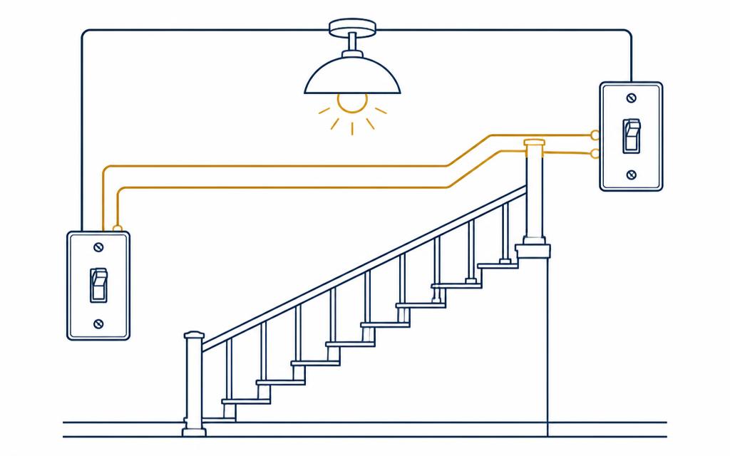
Turn off the breaker and verify power is off before working. If you are not comfortable, hire a licensed electrician.
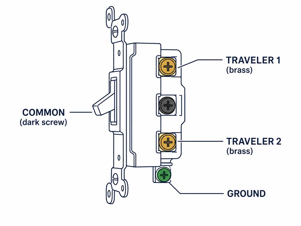
How to verify a dead circuitUnderstand the job: a pair of 3-way switches controls one light from two places. Each switch has one COMMON terminal (dark or black screw), two TRAVELER terminals (brass, interchangeable with each other), and a green ground screw.
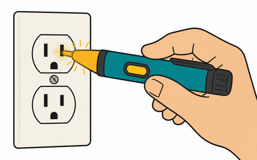
Turn off the breaker feeding the light, then verify the wires are dead with a non-contact tester and confirm with a meter before touching anything.
Identify your cables. In the most common layout, power (a 2-wire cable) enters the first switch box, a 3-wire cable runs between the two switch boxes as the travelers, and a 2-wire switch leg leaves the second switch to the light. If power instead enters the light box (a dead-end or California 3-way), the 3-wire cable still carries the travelers between switches.
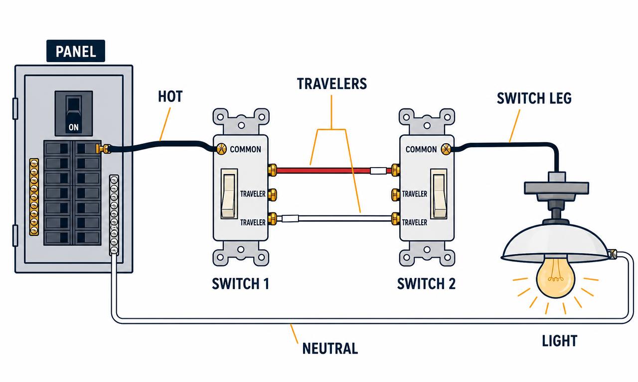
At switch 1: connect the incoming hot (black from the panel) to the COMMON terminal. Connect the two traveler conductors of the 3-wire cable (usually black and red) to the two brass traveler terminals — either order is fine. Splice the neutral (white) through to the light; it never lands on the switch.
At switch 2: connect the same two traveler conductors to the two brass traveler terminals, and connect the switch leg going to the light to the COMMON terminal.
Bond the grounds: connect the bare or green equipment ground to the green screw on each switch and to the box if it is metal.
At the light: switch leg (hot) to the fixture hot, neutral to the fixture neutral, ground to ground. Mark any white conductor used as a hot with black or red tape at both ends.
Fold the conductors neatly into the boxes, screw in the switches, and install the cover plates.
Restore power and test: the light must turn on and off from either switch, in every combination of positions. If it only works from one switch, a common and a traveler are swapped — kill the power and move the wire from the brass terminal to the dark COMMON terminal (or the reverse) at the switch that fails.
Before you disconnect the old switches, take a photo of each one and put a piece of tape on the wire that goes to the dark COMMON screw. That single label is what makes reassembly easy.
- non-contact voltage tester
- multimeter or continuity tester
- screwdrivers (flat and Phillips)
- wire stripper
- needle-nose pliers
- electrical tape
- two 3-way switches (15A or 20A to match the circuit)
- 14/3 or 12/3 cable for the traveler run (match the circuit wire size)
- wire connectors
- cover plates