Electrical fundamentals
The foundation under every job: verify dead circuits, know Ohm's Law cold, understand what your local code requires, and troubleshoot in a repeatable order.
Treat every conductor as live until you have proven it dead with a tester you have just verified on a known-live circuit. Breaker off is not the same as dead.
- Turn the breaker off, then lock or tape it off and label it so nobody flips it back on while you work.
- Verify dead every single time: test the wires with a non-contact tester, confirm with a meter across hot-to-neutral and hot-to-ground, then prove your tester still works on a circuit you know is live.
- Never trust the panel label. Test the actual conductors you are about to touch — mislabeled and double-fed circuits are common.
- Use the one-hand rule near anything that could be energized, and keep your other hand out of contact with grounded metal.
- Wear safety glasses, use insulated tools, and stand on a dry, non-conductive surface.
- Panel work: the main lugs stay energized even with the main breaker off. Treat the top of the panel as live at all times.
- Plug power tools into GFCI protection, keep cords out of water, and never work on wet surfaces or in a damp crawlspace without protection.
- Ladders near service conductors should be fiberglass, never aluminum.
- Ohm's Law: Volts = Amps x Ohms. Rearranged: Amps = Volts / Ohms, Ohms = Volts / Amps.
- Power: Watts = Volts x Amps. A 1,500 W heater on 120 V draws 12.5 A — which is why it fills a 15 A circuit by itself.
- Series circuits share one path, so current is the same everywhere and voltage divides. Parallel circuits share voltage, and current divides — house wiring is parallel.
- Wire gauge is chosen for the breaker, not the load: 14 AWG copper for 15 A, 12 AWG for 20 A, 10 AWG for 30 A.
- Voltage drop: keep it under about 3% on a branch circuit. On long runs, go up one wire size.
- A tripping breaker is information, not a nuisance. It means current exceeded what the wire can safely carry, or a fault exists.
Ohm's Law calculator
Fill in any two values and clear the third to solve for it.
Resistance: 10.00 Ω
Power: 1440 W
- The NEC (NFPA 70) is a model code. It only applies where your state, county, or city adopts it — and many adopt an older edition with local amendments.
- Find your rules by searching your city or county name plus "electrical code amendments" or by calling the building department and asking which NEC edition is enforced.
- The AHJ (Authority Having Jurisdiction) — usually your local inspector — has the final say and can require more than the NEC does.
- Permits are typically required for new circuits, panel or service work, and rewiring. Simple device swaps often are not, but rules vary.
- Common inspection failures: missing or improper AFCI/GFCI protection, overfilled boxes, unsupported cable, missing cable clamps, no anti-short bushings, and unlabeled circuits.
- Some work — service upgrades, meter changes, anything touching the utility drop — legally requires a licensed electrician nearly everywhere.
- Insurance and resale both care about permits. Unpermitted work can be denied on a claim or flagged on inspection.
Essential electrician skills
Five capabilities that separate a safe electrician from a dangerous one. Each includes a role-aware tip and a hands-on tool.
- Start with a visual inspection: look for scorched devices, melted wire nuts, or burned breaker bus stabs before touching anything.
- Use a multimeter, not just a non-contact tester. A voltage test tells you if a conductor is live; an ohms test tells you if a short exists.
- Short circuit: hot touches neutral or ground with very low resistance. The breaker trips instantly. Isolate the circuit, then divide and conquer.
- Ground fault: hot contacts a grounded surface (box, metal fixture, water). A GFCI/AFCI detects the imbalance and trips.
- Overload: the running load is at or above the breaker rating. The breaker trips after some time or under heavy load.
- Never bypass a breaker or install a larger one without verifying the wire is sized for it. The breaker protects the wire, not the device.
- On AFCI breakers, a trip can be an arc fault, a ground fault, or a nuisance. Test the breaker and the wiring separately.
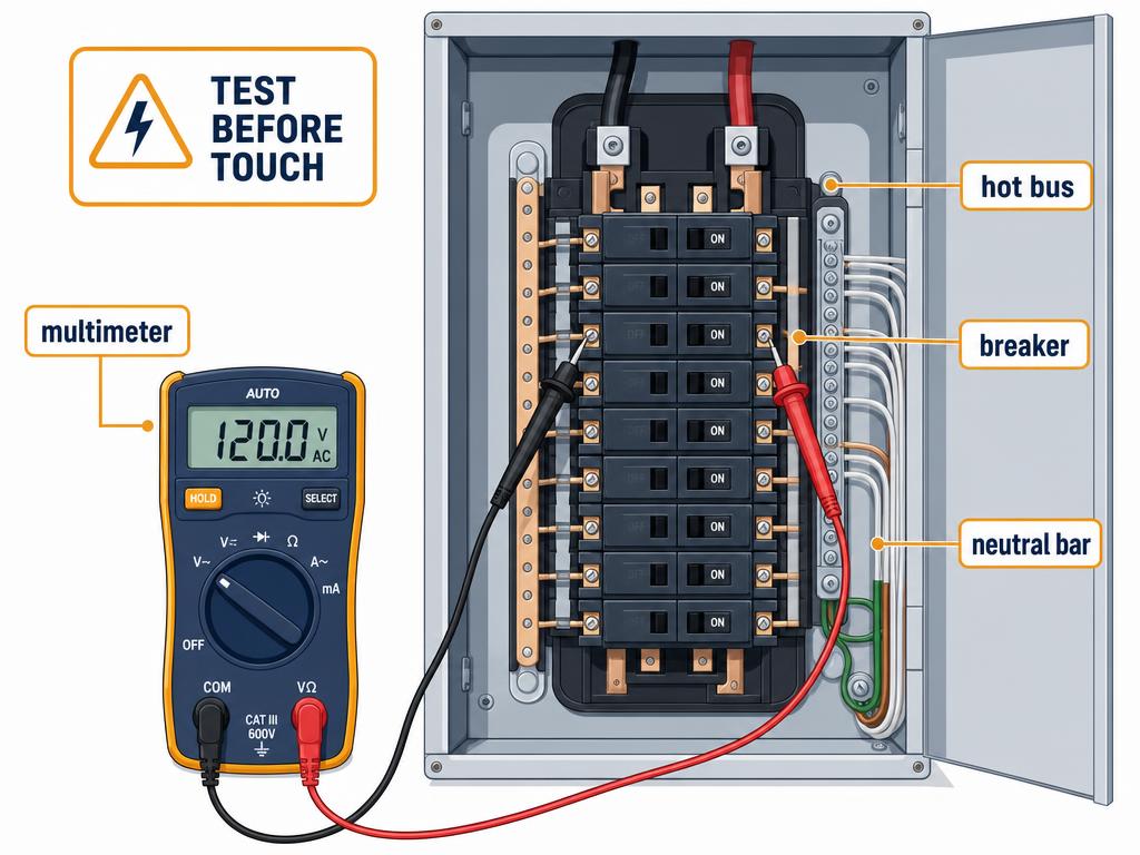
Tripped-circuit diagnostic
Pick the symptom that matches what you see. This is a starting guide, not a replacement for a meter.
- Service size is determined by the calculated load, not by adding up every breaker rating. A 200 A panel with a 100 A calculated load is fine.
- The main service conductors, meter base, and main breaker must all be rated together as a system.
- Panel location matters: working clearance, illumination, dedicated space, and accessibility per NEC 110.26.
- Use the manufacturer’s listed breakers or classified breakers approved for that panel. Mixing brands can void listing and cause failures.
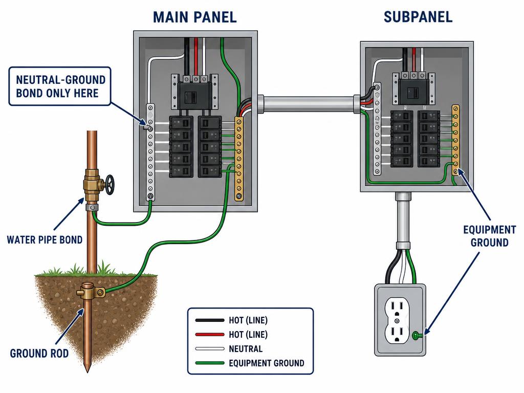
- Ground and neutral are bonded together only at the service equipment. Subpanels and detached buildings keep them isolated.
- Label every circuit at the panel. The NEC requires it, and it makes future troubleshooting and emergency response faster.
- Main lugs remain energized even with the main breaker off. Treat the service entrance area as live at all times.
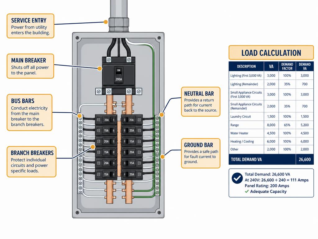
Panel load calculator
Add the major loads. This is a simplified demand estimate; a real load calc uses NEC demand factors and non-coincident loads.
Total demand: 14,800 W
Approx. amps: 79.2 A
Suggested service: 100 A
- Measure from the inside wall of the box to the back of the bend, then add the take-up for the bender size and conduit type.
- A 90° stub-up height is: total height minus take-up. Practice on scrap before cutting your final stick.
- Offset bends let the conduit run parallel to a wall after leaving a surface-mounted box. Measure the offset height and the distance.
- Support EMT within 3 feet of every box and every 10 feet thereafter; PVC typically every 3 feet and within 3 feet of a box.
- Use proper connectors and locknuts; set-screw connectors are common for EMT, and glued fittings for PVC.
- Conduit fill is limited by the total cross-sectional area of conductors. Never exceed 40% for three or more conductors.
- Deburr every cut end so the insulation is not damaged when pulling wire. Use a fish tape and pulling lubricant on long runs.
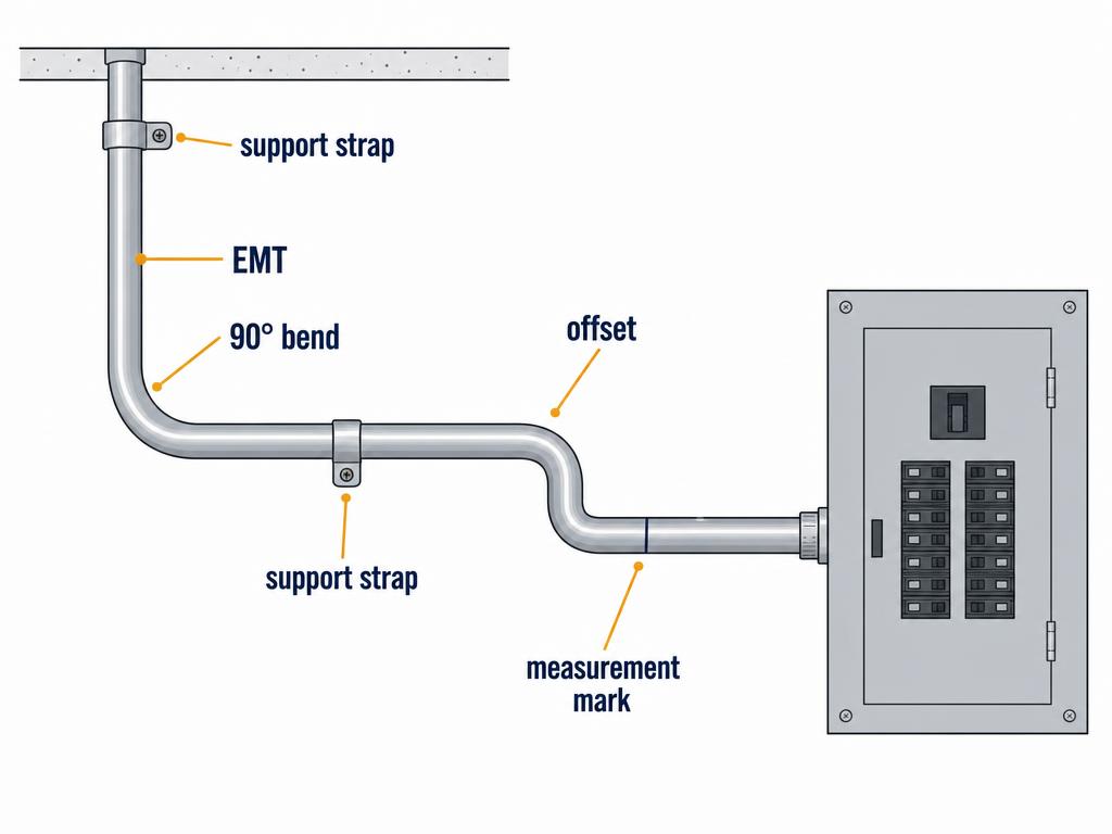
Conduit fill calculator
One to two conductors can fill up to 53% of the conduit cross-section. This calculator uses common EMT sizes and THHN/THWN-2 conductor areas.
Max fill for 3/4" EMT: 0.282 in². Current total: 0.040 in².
- Grounding provides a path for fault current to return to the source. Bonding keeps all metal parts at the same potential.
- The grounding electrode system may include ground rods, a concrete-encased electrode (Ufer), a ground ring, or the metal water pipe.
- At the service, the neutral and equipment ground are bonded together. This is the only place that bond is allowed.
- In a subpanel, the neutral bar is isolated from the ground bar. Bonding them there creates parallel neutral paths and dangerous voltages.
- Every metal box, raceway, and enclosure must be bonded to the equipment grounding conductor.
- Receptacles and switches must be connected to the EGC. Self-grounding devices count only in listed configurations.
- A broken or missing EGC is a shock hazard. If you find old two-wire cable without a ground, do not use the box as the only ground path.
Grounding and bonding checklist
Use this before energizing a new service, subpanel, or major circuit. Bonding keeps conductive parts at the same potential; grounding provides the fault-current path.
0 of 7 completed
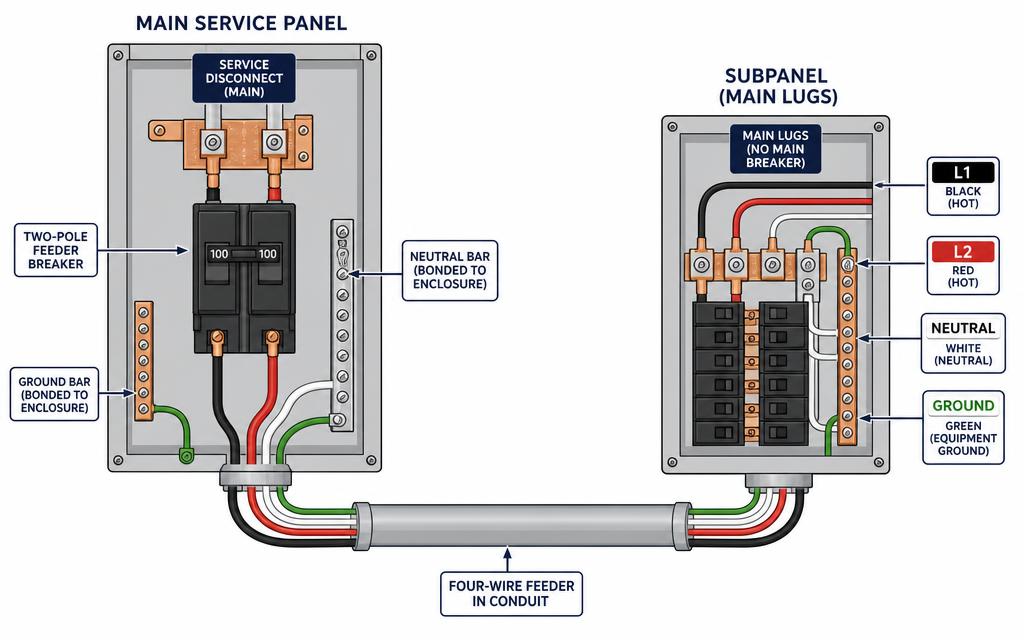
- A subpanel is fed by a feeder, not a branch circuit: two hots, one neutral, and one equipment ground — four wires, never three.
- Size the feeder to the subpanel rating and verify the service can carry the extra load with a load calculation first. 60A covers a small shop; 100A suits an addition or detached building.
- The neutral bar in a subpanel must be isolated. Remove the bonding screw or strap, and terminate equipment grounds on a separate bar bonded to the enclosure.
- The neutral-to-ground bond happens exactly once, at the service. Bonding them again downstream puts neutral current on enclosures and raceways.
- A subpanel in a detached structure needs its own grounding electrode bonded to the ground bar, while the EGC still runs back with the feeder and the neutral stays isolated.
- The main lugs in the service stay energized with the main breaker off. Test everything you plan to touch, and torque every lug to the printed spec.
- Check voltage drop on long runs — over roughly 100 feet, upsizing a conductor size is usually cheaper than chasing dim lights and hot terminations later.
Feeder & subpanel sizer
Typical residential picks for a 4-wire feeder in conduit. Always confirm against NEC 310.16 and your local amendments.
Copper feeder
#6 Cu THHN
Aluminum feeder
#4 Al
Equipment ground
#10 Cu
Estimated voltage drop: 2.8 V (1.2%)
Remember: the subpanel neutral bar must be isolated and the bonding screw removed. Grounds go on their own bar bonded to the enclosure.